Abstract:Operational amplifier is Integrated Circuits which include a lot of transistors. It is one of the most widely used devices. Operational amplifier is different with the usual
amplifier.It is a amplifier of direct coupling of high gain, high input resistance, low output resistance. In many years ago, it can finish addition, subtraction, multiplication,
division, differentiation and integration, but its application is far beyond the scope. This paper mainly introduces the actual applications of Operational amplifier including
the basic principle of Operational amplifier and some application of operation.
A principle of operational amplifier
An operational amplifier (OP AMP) is a circuit unit with a high magnification. Although different operational amplifiers are different, the characteristics of the operational amplifier are the same for the external circuits, and the integrated circuits of many transistors are included in the operation and amplifier. Because it can finish mathematical operations such as addition, integration, differential and so on, it is called operational amplifier. Besides being able to be applied to arithmetic circuits, it can also be applied to process circuits and generating circuits.
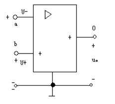
The operational amplifier consists of 4 parts, the bias circuit, the input stage, the intermediate stage and the output stage. Although there are many models of the operational amplifier, its internal structure is also different. The following is the circuit graphic symbol of op amp, and the "triangle" symbol means "amplifier". The operational amplifier has two input, a, B and an input port o. The a end is called the backward input (also called the reverse phase input). When the voltage U- is added between the a end and the common end, and its actual direction is higher than the common end of the a end, the output voltage is U. The actual direction is from the common end to the o side, that is, the direction of the two directions is just the opposite. The B terminal is called a non backward input terminal (also called inphase input). When the input voltage U+ is added to the B terminal and the common end, the actual direction of U and U+ is exactly the same as that of the common end. For the sake of difference, a terminals and B terminals are marked with "-" and "+" numbers, but they should not be mistaken for the positive and negative polarity of the voltage reference direction. The positive and negative polarity of voltage should be marked or arrowhead.

Two, operation in operation
1: the proportion of the circuit
The proportional operation circuit is a circuit amplifying the input signal in proportion. According to the input signal, different input terminals can be divided into reverse proportional circuit, in-phase proportional circuit and differential proportional circuit.
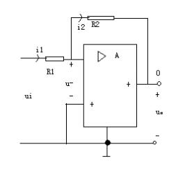
Here is an example of backward proportions. The following figure represents a reverse proportional device, which is composed of an operational amplifier and a resistor. The output voltage of the op amp is fed back to the input circuit through resistance R2. Obviously, because of the existence of resistance R1, the input voltage UI of resistance is different from the reverse input voltage u- of op amp.
The 2. Circuit and poor
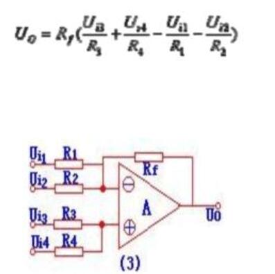
Circuit diagrams as showed below. The function of this circuit is to sum up the inverse phase of Ui1 and Ui2, and to sum up the Ui3 and Ui4, and then the superposition and different results are carried out, and the input and output voltage relation are as follows:

The 3. Integral and differential circuits are basically resistors. If the resistance of the end is replaced by a capacitor, the result will become an integral circuit and a differential circuit.
(1) differential circuit: the difference differential circuit and the integral circuit is a resistor and a capacitor location swap. The differential is the integral of the inverse operation. The output voltage and input voltage was differential relationship. The circuit diagram is shown in Figure 1.

(2) integral circuit: a circuit is shown in Figure 1, it can realize the integral operation and generate triangle waveform. Integral operation is the integral relation between output voltage and input voltage. It uses the charge and discharge of capacitors to achieve integral operation.
4. active filter
Active filter is a filter circuit composed of amplifiers, resistors and capacitors, which can be used in information processing, data transmission, interference suppression and so on. However, due to the limitation of the operational amplifier frequency band, this filter is mainly used in the low frequency range. It is a new type of power electronic device used to dynamically suppress harmonics and compensate reactive power. It is called active because it can compensate the harmonics of varying size and frequency and the variable reactive power.
5. voltage follower
The voltage follower is the same as the output voltage and the input voltage. The voltage magnification of the voltage follower is close to 1. Its characteristics are high input impedance and low output impedance. Generally speaking, the input impedance must be several trillion ohms, which is very easy to do. The output impedance is low, usually to several ohms, or even lower. Function: in circuit, voltage follower usually acts as buffer level and isolation level. Because the output impedance of the voltage amplifier is generally high, usually from thousands of Europe to tens of thousands of Europe, if the input impedance of the post stage is relatively small, then the signal will have a considerable portion of the loss in the output resistance of the former stage. At this time, voltage followers are needed to buffer them. Play an important role.
6. comparator
When the feedback resistance of the operational amplifier is removed, or when the feedback resistance tends to infinity (that is, the open loop state), the open loop magnification of the amplifier is also theoretically considered infinitely large (in fact, it is very large, for example, the amplification of the open loop of the LM324 amplifier is 100dB, 100 thousand times). At this point, Op Amp will form a voltage comparator, if output is not high level (V+), it means low level (V- or grounding). When the positive input voltage is higher than the negative input voltage, the operational amplifier outputs low level.
7. in-phase AC amplifier
The characteristic of in-phase AC amplifier is high input impedance. The R1 and R2 consist of 1/2V+ voltage divider circuit, which is biased by R3. The voltage magnification Av of the circuit is also determined by external resistance: Av=1+Rf/R4, and the input resistance of the circuit is R3. The resistance of the R4 range for thousands of ohms to tens of ohms
Integrated circuits (ics) linear - amplifiers - instrumentation, op amps, buffer amps
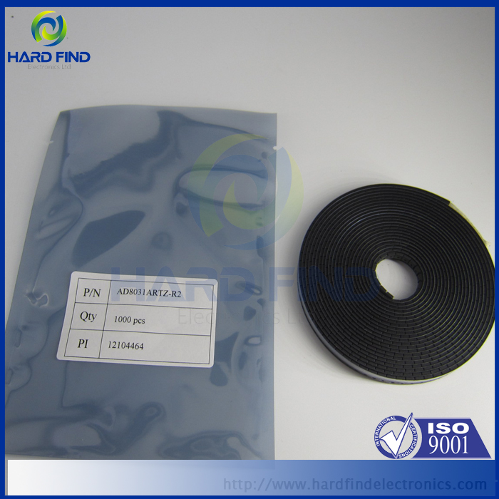
Related products: AD8031ARTZ-R2
APPLICATIONS
High speed, battery-operated systems
High component density systems
Portable test instruments
A/D buffers
Active filters
High speed, set-and-demand amplifiers

AD8031ARTZ-R2

